Blog 5: Prototyping
- Feb 24, 2024
- 13 min read
Updated: Feb 25, 2024
Introduction
Hi! Wow so fast, final blog already! To end off my CPDD journey with a bang, this will be my prototyping blog. Before you start reading this blog, I highly recommend going back to the some of the previous blogs as this 5th blog will be cumulation of all the skills in those previous blogs.
Much of this blog will be quite advanced in terms of the content and skills so if you still struggle with some of the basics, please visit my previous blog page which is in this link:
Content
In this page, I will:
1. Briefly describe my team chemical device.
2. Show how the team planned, allocated the tasks, and executed the project.
3. Document the entire design and build process of the chemical device and include videos, pictures, and screen captures of the processes.
4. Include “Hero shot” of every milestone of the processes, example the part A that was 3D printed, part B that was laser-cut, electronics components moved/worked according to the program. Hero-shot is taken with the person-in-charge holding/working/making the parts.
5. Include the name of the person who was in-charge of every part of the project.
6. Document my individual contribution to this project.
7. Provide the link to the page of the blog of my teammates.
8. Describe problems encountered and how the team solved them.
9. Include all the project design files as downloadable files.
10. Embed the final prototype design file, i.e., the final fusion 360 design file showing the entire prototype.
11. Type my Learning reflection on the overall project development.
1. Our team chemical device
· Team chemical device: Automatic Tea Maker
· Background:

Figure 1: Statistics on relation between tendonitis and age of patient.
· As shown from the image above, the number of patients with musculoskeletal disorders such as tendonitis increase with age with the most prevalent being in the age group of 51 to 60.
· Brewing tea normally requires the drinker to regularly steep the tea bag so that the tea is properly brewed.
· However, this may pose a problem to the elderly with tendonitis as such a repetitive activity of steeping the tea may cause stress to their joints resulting in pain.
· Our product aim to provide a easier alternative of people with tendonitis to brew tea.
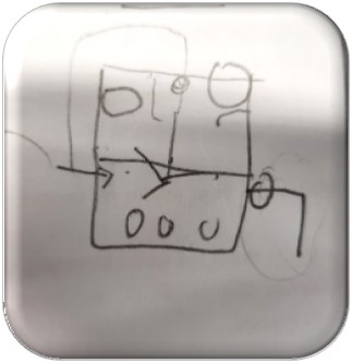
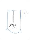
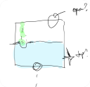
Initial hand sketches of our tea maker
-


Initial CAD sketch of our tea maker

Final hand sketch of product:

Task fulfilment of our tea maker
1. Gears
- For the gear’s component, we used a speed ratio to ensure the impeller spins fast to ensure the solute in the tea leaves is leached out.
2. 3D printing
- For this component, we 3D printed the impeller and the gears.
3. Laser cutting
- For this component, we laser cut the box out of acrylic so to store the Arduino board wires and gear in one section and the other section for the ease of refilling of the water and the replacement of the used tea bag
4. Arduino coding
- We developed a temperature interlocking system between the impeller and the 360-degree continuous motor. We coded the Arduino so that if the temperature is within a certain temperature range, the impeller will turn on but if the temperature is outside of said temperature range, the impeller will not turn on. This is taken from inspiration from the W319 MRTs units.
5. Hand tooling
- Hot glued the box that was holding the gears and Arduino together
- Used soldering to create solder the temperature sensor to some wires and solder together wires to create a modified wire.
6. Team Planning, allocation, and execution
1. Meet the team
- CEO (Me, Ang Jing Yue)
- CFO (Yu Jie: https://linyujie2005.wixsite.com/my-site)
- COO (Mabelle: https://mabelle22.wixsite.com/mabelleblogs )
- CSO (Dhasna: https://dhasna22.wixsite.com/blog )

2. Task allocation

- We opted for a divide and conquer method as we felt that if all our focus was centred on one portion, it will be less productive.
- In addition, we could also split the work to account for everyone’s strong points.
- An example of this would be that Mabelle and Dhasna are better at Fusion 360 so therefore, the CAD drawings for the impeller and gears are done by them.
- Some of the adjustments done near the end of this prototyping assignment was that since the task of Arduino was very difficult, me, Yu Jie and Mabelle decided to work on the Arduino task together.
- In the meantime, since we pushed the Arduino task to the end, me and Yu Jie we worked on the laser cut box together.
3. Finalised BOM

4. Gantt chart, details, and simplified timeline

Figure 2: Gantt chart

Figure 3: Details of Gantt chart

Figure 4: Simplified Timeline (All task achieved is above the date, all task started is below the date)
3. Design and Build Process
Note: these tutorials do not cover the basics of using Fusion 360. If you need to go through the basics of Fusion 360, please visit here: https://jingyuecp5065.weebly.com/
Where it covers the basics of Fusion 360, 3D printing, laser cutting and more!!!
Part 1. Design and Build of Part A (done by Mabelle). Link:https://mabelle22.wixsite.com/mabelleblogs/post/project-development
1. Press Create Sketch on the Top plane or the x-y plane.

2. Select the centre diameter circle and alter the diameter to you the size of your impeller to be. (In this case, I selected it to be 35mm)

3. Press finish sketch.

4. Extrude the circle by 2mm. It should look like the second image.


5. Press create sketch on the bottom of the cylindrical solid.

6. Create a 6mm diameter circle at the centre of the circle.

7. Click finish sketch and extrude the 6mm diameter circle by -12mm. Remember to select the operation as join. (It should look like the second pic)


8. Select the hole option and place the midpt of hole in the centre of the circle. Extents set to all.

9. It should look like this.

10. Press create sketch on the top plane and select the 3-pt arc.

11. Place a 3-pt arc on the sketch linking the outer circle to the inner one.

12. Select offset on the arc you have created and offset by 1.5mm.


13. Select Trim and extend option to Trim off the arc that is outside the circle and extend the arc to the inner circle.

14. Use the circular pattern function and select the 2 arc and select the centre point to be at the origin point of the sketch. Select the number of impeller blades via the quantity portion. (In this case, I used 4 impeller blades)

15. It should look like this.

16. Extrude and select the 4 sketches of the impeller blades. Select extend type to To Object, object as the face of the inner circle and select extend to Extend Faces. Then, click ok.

17. It should look like this.

18. Press extrude and select the 4 faces of the base plate and select cut for the operation option. Extrude it to -6mm.


19. Click create sketch on the 6mm diameter circle and create a 3mm diameter circle from midpoint of 6mm diameter circle.

20. Extrude the area between inner and outer circle and extrude it to whatever length your impeller needs. Remember to set the operation to join. (In this case, I chose my impeller length of 50mm from the base of impeller)

21. Your final impeller design should look something like this.

22. Since I am 3d printing this design, save this design as an STL file.

23. Opening the STL file will link you to the ultimaker cura app.

24. The left window is where you choose your settings such as infill density, print speed.

25. Now, you just must save to disk your Cura design and have fun printing your impeller.
Note: For more info about 3D printing please visit this site: https://jingyuecp5065.weebly.com/week-5


Part 2. Design and Build of base plate and gears (done by Dhasna)
For more info about the individual portions of the gears and base plate, please do head over to this link:https://dhasna22.wixsite.com/blog/post/blog-5-project-development
1. Open up Fusion 360 and go to utilities and go to add-ins.

2. Once clicking add-ins, a menu should pop up like the one below and go under add-ins tab.

3. Scroll down until you see the spur gear option.

4. You will see two spur gear options. One that is running on C++ (the hexagon symbol) and the other running on python (the yellow and gray icon). You can use either but in this case I will be using the python one.

5. After selecting, click run and the below window will pop up which means the installation of the add-in is successful.

6. Select the spur gear option under the create tab. The below window should pop up.

7. You can adjust the settings according to what you prefer. In this case, I will be adjusting the settings as shown below (The hole diameter is 0mm, so it is easier to form the gear plate)

8. Click ok and it will generate the gear as shown below.

9. Reactivate the spur gear function.

10. In this case, I will be generating my second gear to allow a speed ratio of 2. I simply decreased my number of teeth by half from 32 to 16 and the root fillet ratio from 0.9mm to 0.45mm. Below are the specifications of the second gear.

11. After clicking ok, below is what you are supposed to see.

12. Select the smaller gear and click move/copy.

13. A menu like this will pop up.

14. Set move object as components. Now for your X-distance set it to be equal to the total distance of the larger gear pitch radius and the smaller gear pitch radius (In this case is 32+16= 48mm)

15. If it is done correctly, the pitch reference circles should line up nicely with one another.

16. After that, Select the rotate option under move type and the inner cylinder of the gear as the axis and, set the angle to be 11.3˚

Note: The angle of 11.3 is gotten through guess and checking, so you may have to tweak and adjust the angle of rotation, so the two components do not overlap.
17. Click ok and your gears should look the ones below.

Creating the base plate:
1. Create a new component by right click the gear v1 text. Name it base.

2. Click create sketch on the bottom plane. (If a window pops that says, revert position, click capture position)

3. Place two circles from the centre of the gears, ensure that the circles are slightly bigger than the gears.

4. Create two lines tangent to each circle. The lines should snap and give the symbol below.

5. Hide the gear components.

6. Highlight the whole design. Before extruding, set the start option to offset and extrude distance to 3mm.

7. Press P on your keyboard and select the top face of the plate to project.

8. Select both the gear holes and click ok.


9. Hide the two gear components and hit the O key of your keyboard to start up your offset command.

10. Select both the gear holes set to offset by -0.2mm

11. Extrude up the pins up 10mm.


12. Create a sketch on the top of the plate and offset the base by 10mm for the larger gear and 5mm for the smaller gear.

13. Click finish sketch and extrude up the riser by 3mm so the gears can rest on them.

14. Your finished gear base plate should look like this.
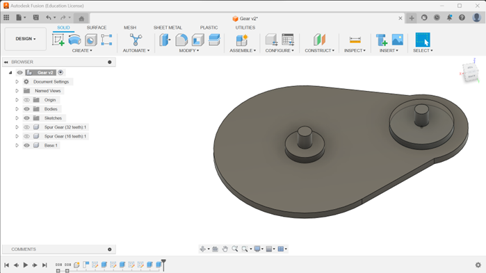
15. Your finished gears layout should look like this.

16. To check if your gear works, select the ground option when right clicking on the base component. When selected, a pin icon will appear.

17. Go to assemble drop down and select the as-built joint.

18. Set type as revolute and select the large gear, base component for components and pin cylinder for snap. If all goes well, the preview animation will play and the gear will spin.

19. Repeat the above for the smaller gear.

20. Go to assembly and select motion link.

21. Select the two joints which are the faces with the flag icon. The gear will start to turn.

22. Now, we have to alter the equation of the angle of the large gear and small gear respectively. Let x=no. of teeth of smaller gear, y=no. of teeth of larger gear, z=angle
For the larger gear, the equation: z=360(x/y)
In this case, my large gear equation is 360(16/32)˚
This equation is quite universal for all gear types. Remember to tick the reverse option


23. This would be finished design.

24. To proceed on to 3D printing of the gear setup, please refer to the step 22 to 25 of the making of the impeller due to them being the same steps.
Part 3. Design and Build of box (done by Me, Jing Yue and Yu Jie). Link: https://linyujie2005.wixsite.com/my-site/post/blog-6
1. Create sketch on the top plane. Replicate the below picture.
Have the dimensions of the rectangle as 297mm by 210mm to replicate the size of a A4 size paper.
Ensure the lines going across the rectangle are at the mid points of the length and breadth, respectively.

2. Extrude the both the rectangles by 3mm. The large piece is going to be the bottom of the box while the smaller piece is going to be a divider placed between the two holes.

3. Create another sketch on the top plane. Replicate the dimensions of the below picture.
These are going to form the sides of the box

4. Extrude both rectangles by 3mm.

5. Create a sketch on the surface of the shorter rectangle. Sketch out a rectangle of 10mm by 5mm on the length of the rectangle and have a distance of 10mm from the breadth of it.
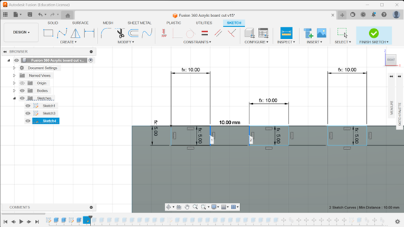
6. Continue placing the rectangle on the length of the rectangle and ensure that each rectangle have an equal spacing of 10mm from one another until the end of the rectangle.

7. Extrude out the rectangles by -4mm and ensure the operation is set to cut.

8. Repeat the above step for all the rectangles and it should look like this.

9. Repeat step 7 and 8 for the other rectangle. It should look like this.

10. Repeat step 1 but this time only doing up the A4 size rectangle without any lines or holes. This will be the top of the box.

11. Move the two walls to be in line with the top of box.

12. Copy the two sides and place them together to form a box.

13. Create a sketch on the back of the top piece. Sketch out a rectangle where the piece overlaps each other.

14. Repeat the above step for all 4 corners of the box.

15. Cut out the area where the rectangles are by using extrude and using the cut operation.

16. Mark out the places where the teeth of the sides of the box overlap the top of the box and sketch the size of them. Repeat for all 4 sides of the box.


17. Move all 4 of the sides of the box out of the top piece.

18. Cut out all those rectangles by using the cut operation in the extrude function.

19. Reorganise your pieces for laser cutting.

20. Cut out the 2 holes from the bottom of the box.

21. Preparation of fusion 360 file for laser cutting.
Export your file as a Dxf file.

22. And now, you are ready to begin laser cutting your box.
To recall how to use CorelDRAW and a laser cutter, you can refer to this blog site: https://jingyuecp5065.weebly.com/blog-4
Note: This is actually a very hard way to create a box. A simpler way to create a box is through this link: https://makeabox.io/
All you need to do is to specify the dimensions of the box you want, and they will create it for you.
Part 4. Programming of motor, temperature sensor and temperature interlocking system (Done by Yu Jie, Jing Yue, Mabelle). Link: https://linyujie2005.wixsite.com/my-site/post/blog-6 & https://mabelle22.wixsite.com/mabelleblogs/post/project-development
1. Research
- We had to do some research on how to program the temperature sensor in terms of C++ coding
- The video below greatly helped us setup the code of the temperature sensor to display the temperature on the serial monitor.
-
- For the code, we tried to apply our knowledge of if-else loops to the code. To add on, we also tried asking ai for help. Ai software such as Blackbox.ai and ChatGPT
2. 1st iteration of setup and code
Code | const int temperaturePin = 0; const int motorPin = 9;
void setup() { Serial.begin(9600); pinMode(motorPin, OUTPUT); }
float getVoltage(int pin) { return (analogRead(pin) * 0.004882814); }
void loop() { //void motorOnThenOff(); int speed; {float voltage, degreesC, degreesF; voltage = getVoltage(temperaturePin); degreesC = (voltage - 0.5) * 100.0; degreesF = degreesC * (9.0/5.0) + 32.0;
if (degreesF > 75) { digitalWrite(motorPin, HIGH); delay(1000); digitalWrite(motorPin, LOW); } Serial.print("voltage: "); Serial.print(voltage); Serial.print(" deg C: "); Serial.print(degreesC); Serial.print(" deg F: "); Serial.println(degreesF);
delay(500); }
} |
Setup |  |
Some of the problems that happened to this iteration:
- Code not configured to the specific type of temperature sensor
- Library of DallasTemperature and OneWire.h was not installed
- Used motor instead of servo which resulted in the revolutions being too fast
3. 2nd iteration of setup and code
Code | #include <OneWire.h> #include <DallasTemperature.h> #include <Servo.h>
#define ONE_WIRE_BUS A5
OneWire oneWire(ONE_WIRE_BUS);
DallasTemperature sensors(&oneWire);
float Celsius = 0; float Fahrenheit = 0; Servo myservo; int Ledpin=13; int CTemp=0; int temperature = 0; int pos = 0;
// Define minTemp as a global variable float minTemp = 20;
void setup() { sensors.begin(); myservo.attach(9); const int maxTemp=30; Serial.begin(9600); }
void loop() { sensors.requestTemperatures();
Celsius = sensors.getTempCByIndex(0); Fahrenheit = sensors.toFahrenheit(Celsius);
Serial.print(Celsius); Serial.print(" C "); Serial.print(Fahrenheit); Serial.println(" F");
// Map temperature value to servo angle
// Control LED based on temperature if (minTemp <= Celsius) { digitalWrite(Ledpin, HIGH); for (pos = 0; pos <= 180; pos += 1) { // goes from 0 degrees to 180 degrees // in steps of 1 degree myservo.write(pos); // tell servo to go to position in variable 'pos' delay(15); // waits 15ms for the servo to reach the position for (pos = 180; pos >= 360; pos += 1) { // goes from 180 degrees to 0 degrees myservo.write(pos); // tell servo to go to position in variable 'pos' delay(15); }}}else { digitalWrite(Ledpin, LOW); }
delay(1000); } |
Setup |  |
Some of the problems that happened to this iteration:
- Setup of breadboard was wrong
- Code included the mapping of temperature to servo angle which is wrong
4. Finalised iteration of setup and code
Code | #include <OneWire.h> #include <DallasTemperature.h> #include <Servo.h>
#define ONE_WIRE_BUS 9
OneWire oneWire(ONE_WIRE_BUS);
DallasTemperature sensors(&oneWire);
float Celsius = 0; Servo myservo; const int Ledpin = 9; // Changed Ledpin to const int int temperature = 0; int pos = 0;
// Define minTemp as a global variable float minTemp = 20; // Corrected minTemp threshold
void setup() { sensors.begin(); myservo.attach(9); // Attached servo to pin 9 pinMode(Ledpin, OUTPUT); // Initialize LED pin Serial.begin(9600); }
void loop() { sensors.requestTemperatures();
Celsius = sensors.getTempCByIndex(0);
Serial.print(Celsius); Serial.println("C");
// Control servo motor based on temperature if (Celsius <= 20 && Celsius != -127) { // Changed to use minTemp variable for (pos = 0; pos <= 180; pos += 1) { // goes from 0 degrees to 180 degrees myservo.write(pos); // tell servo to go to position in variable 'pos' delay(15); } for (pos = 180; pos >= 0; pos -= 1) { // goes from 180 degrees to 0 degrees myservo.write(pos); // tell servo to go to position in variable 'pos' delay(15); } } else { // Do something else when temperature is below threshold // Turn off LED when temperature is below threshold digitalWrite(Ledpin, LOW); } } |
Setup |   |
Problems encountered:
- Arduino board only have one ground port that is working so we have to create a modified wire by soldering
Part 5. Integration of all parts and electronics (done by everyone)
Hand tooling
1. Soldering
- Soldering of wires to temperature sensor
- Soldering of wires to create a modified wire as Arduino Board only have one available ground port
2. Hot Gluing
- We had to hot glue the sides of the box together and had to hot glue the box to the cover.
3. Assembly
- Servo and driver gear are positioned perpendicular to the gear board so that there is enough space for the gear train.
- The impeller is immersed to a depth two-thirds of the container height.
- Temperature probe is partially submerged in the tea.
- Gears are configured to function as a small speed multiplier.
Demonstration of tea maker
Downloadable files
4. Problems and solutions
Problems | Solutions |
Delivery of materials | One of the components which was the plastic tap we needed was not available at school. We had to turn to the internet in search for a cheap and fast delivery time plastic tap. We used websites such as Shopee to get what we needed. |
Arduino Programming | The key problem when we were doing the Arduino Programming was that we didn’t know whether it is our code that is wrong or the setup on the breadboard that is wrong or both. This is due to our inexperience with the breadboard as we had to self-learn how to use the breadboard. Furthermore, two of our ground wire ports in our Arduino Board were not working.
To solve these issues, we had to enlist the help of a fellow classmate which was Yu Chen to help us with the setup and the code, mainly the setup. To solve the two ground wire ports not working, we had to use the solder iron to create a modified wire which connected two wire ports into one. |
Assembly | Box assembly - Our dimensions of the box did not allow the cover of the box to sit into the indents of the box. - To solve this, we had to modify how we assembled the walls of the box together. We had to stick 2 of the walls on the inner side of the box and the other 2 on the outside. Gear placement - The main gears had a base plate so we had to made certain adjustments to lift the gear at the impeller higher so the teeth of the impeller would fit in. - In addition, the gear connected to the servo did not have any place for it to stand horizontally so to solve this, we simply made a stand for the motor and made it stand vertically. Leakage - When we were first testing the prototype, there was water leaking from the tap due to the tap not being tightly inserted into the hole. - To solve it, we simply hot glued the tap to the container to cover up any holes that would cause any leaks. |
Presentation
Photodump


6. Below is my Learning Reflection on the overall Project Development.
Project Development has been both a fun and very tiring experience. Although my team met various challenges such as tight deadlines and coding difficulties along the way, we eventually managed to create a successful prototype. Before this when Mr Chua told us that we will have to create a real prototype I was quite intimidated as it was, I personally have never done something like that before.
Looking back, although I agree that it was as hard it seems, it gave a sense of fulfilment when we were finished with it. Furthermore, by working on this prototype, it has given me many hard skills at my disposal such as CAD drawings, C++ coding with an Arduino board. In addition, this prototyping assignment I felt really honed our skills in those areas. An example of this would be for the Arduino Programming side, we could use AI to help us, but we needed the skills taught to us to tweak the code to do what we need it to do.
To add on, this prototyping assignment really gave me a chance to utilise my teamwork, communication and time management skills and develop my leadership and project management skills. Such skills really helped in this assignment as without such skills, we would not have finished the prototype by the deadline. Such soft skills would come in use when doing internship and my Final Year Project (FYP).
In my opinion, one takeaway from this is that it never hurts to start earlier. As Walt Disney says, “The way to get started is to quit talking and begin doing.” When approached with an extremely large task at hand, you should break up the task into smaller manageable parts and set clear goals.
7. Conclusion
In essence, the project was a remarkable experience, blending both the intense pressure of deadlines with the enjoyment of problem-solving. I firmly believe that my team and I demonstrated this by consistently delivering 100% effort. As I always say, always put in 100%. When you cry, you cry. When you laugh, you laugh. When you eat, eat like it is your last meal. Even though, the outcome is not what you expect, you know you have done your best and you will have no regrets.
This is the end of my time in Chemical Product Design and Development, but it is only the beginning for you. I wish the best of luck and goodbye!!!


Comments